Tutorial
Before creating your first winding program, it helps to prepare a few basics. The program wizard, found under Filament Winding > Programs > Add a new Program, already ships with ready-made templates for machines, mandrels, payout eyes and raw materials, so most of the setup work is done for you.
To make the most of this wizard, have the following information on hand:
- the HMI brand installed on your machine and how its axes are configured;
- the mandrel type you'll be using and its overall dimensions;
- the band width your machine works with.
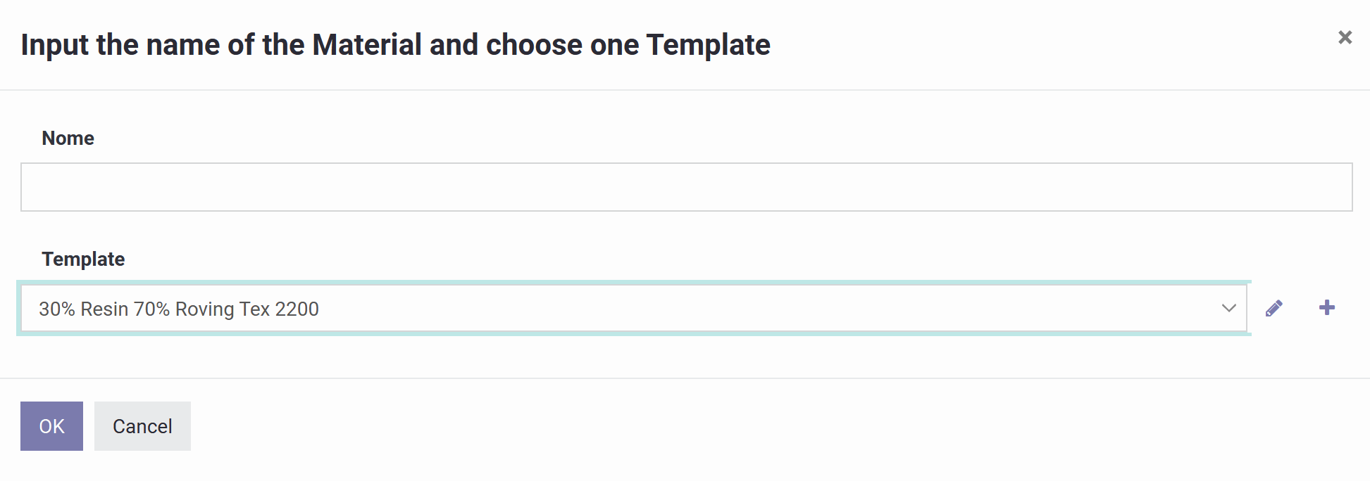
This is the starting screen for registering a new material. Selecting Create opens the material form, where you configure its composition, unit of measure and bill of materials, as detailed in the next section.
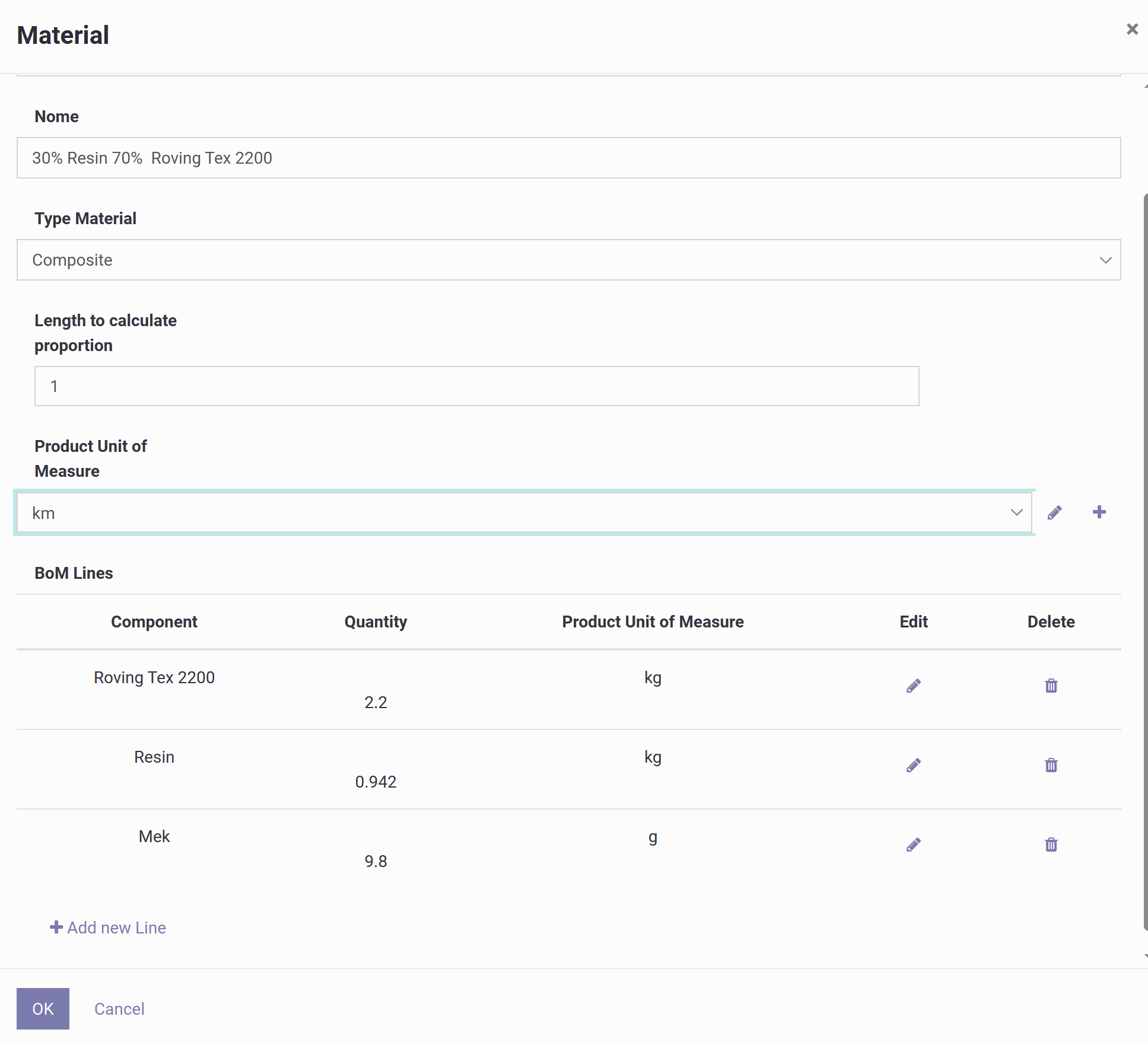
This form is where you register a composite material and tell the system three things: what the finished product is, which unit of measure is used to track consumption, and what the recipe (bill of materials) looks like.
Here is what each field means:
1) Name
A free-text label for the material, usually describing the resin/fiber ratio and roving type, e.g. "30% Resin 70% Roving Tex 2200".
2) Material Type
Set to Composite, meaning this entry is a blend of several components rather than a single raw material. Available types are:
- Fiber — roving, tow, fabric or veil; tracks fiber consumption in kg, tex or g/m.
- Resin — epoxy, polyester, vinyl ester; tracks resin consumption in kg or L, optionally with density for volume/mass conversion.
- Prepreg — fiber that already contains resin; tracked directly in m, m² or kg.
- Composite — a recipe made of several components, defined through a bill of materials.
- Filler — solid additives such as silica, microspheres, talc or pigment.
- Release — release agents or separation film, e.g. wax, PVA or release film.
3) Length to Calculate Proportion
Defines the base quantity used to scale the recipe. If the product unit is length and this value is 1, the bill of materials below describes the consumption for 1 km of finished material; setting it to 10 would mean the same recipe applies to 10 km.
4) Product Unit of Measure
The unit in which the finished composite is measured, typically length (km), since in filament winding what's consumed is usually the band/laminate length or the trajectory length.
5) BoM Lines (Bill of Materials)
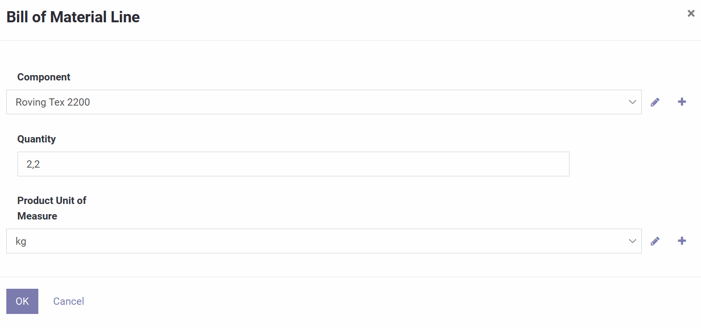
The actual recipe: each line lists a component, how much of it is consumed, and its unit of measure, with options to add, edit or delete lines. For example, per km of composite: 2.2 kg of Roving Tex 2200, 0.942 kg of Resin, and 9.8 g of MEK (catalyst).
6) OK / Cancel
OK saves the material and its recipe; Cancel discards the changes.
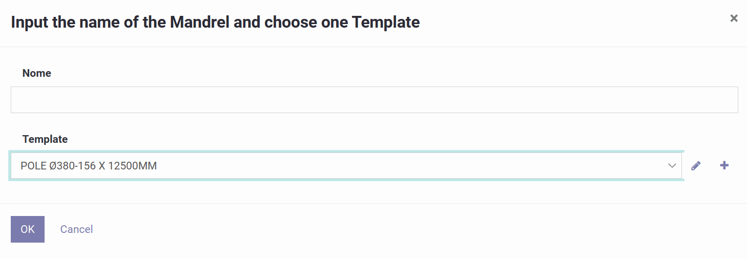
This screen is a wizard that creates a mandrel from a ready-made template.
1) Name
The label that will identify this mandrel in your lists and programs. Good examples include a type, diameters and length, e.g. "POLE Ø380-156 x 12500". Including these details up front makes the mandrel easy to recognize later.
2) Template
Choose a pre-configured mandrel model, for example "POLE Ø380-156 X 12500MM". Selecting it automatically loads the geometry: shape/type, start and end diameters, total length, and any other dimensions the template defines.
Next to the Template field, the pencil icon lets you edit the selected template's dimensions, while the plus icon lets you create a new template to save as a standard.
OK creates the mandrel from the chosen template; Cancel closes the wizard without saving.
This is where you edit the mandrel geometry that the software uses to calculate the winding path.
Status shows Draft while the mandrel is still editable. Name is the label shown in lists and programs. Format determines which shape model and dimensions are required, and updates the sketch accordingly.
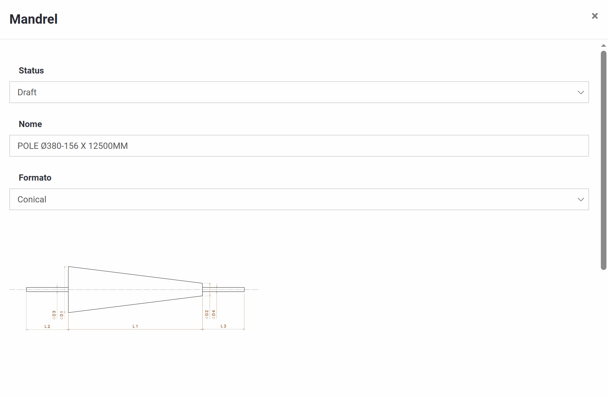
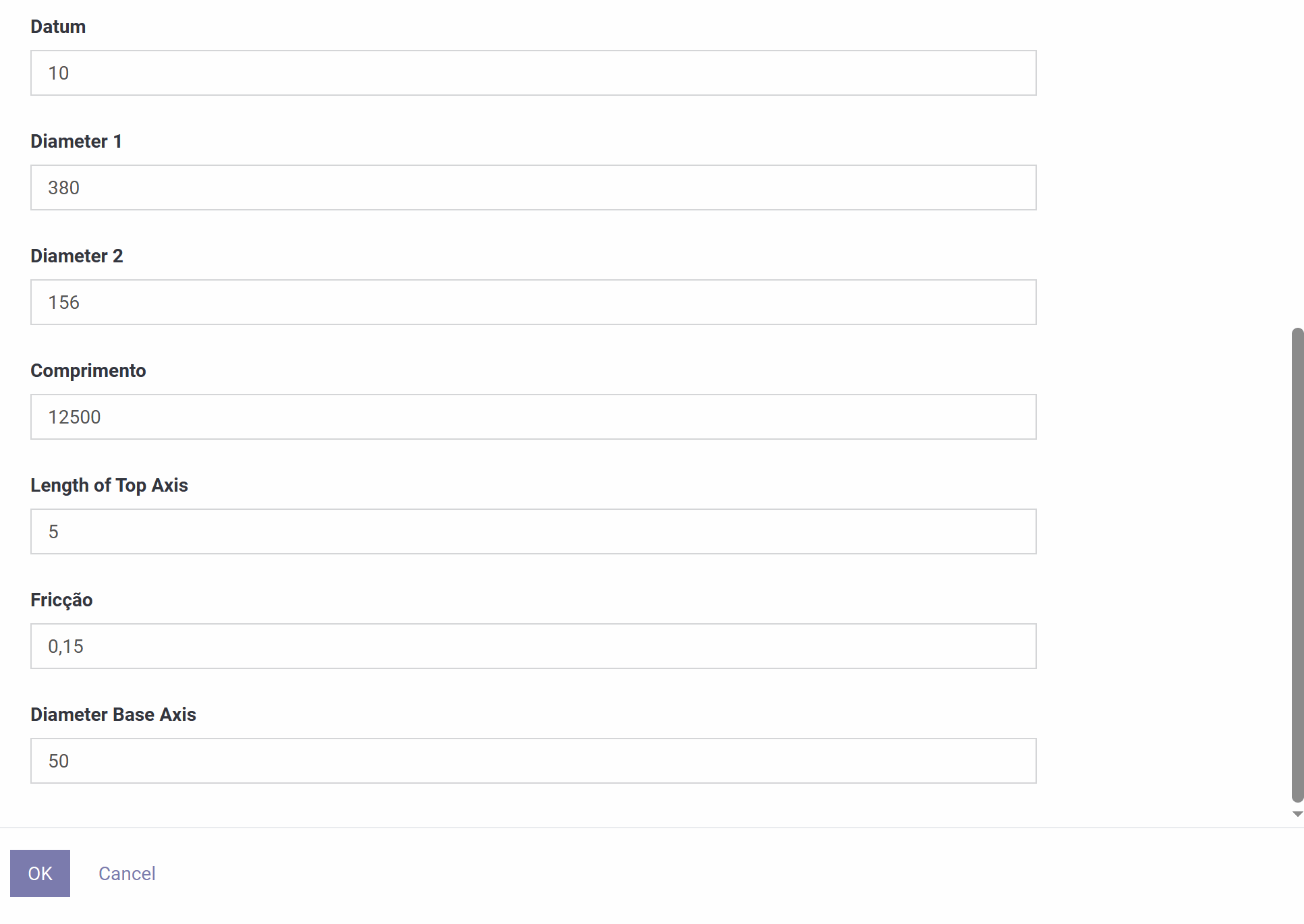
The geometry parameters (typically labeled D1–D4 and L1–L3) feed directly into the sketch shown on screen. Common fields include:
- Datum — a reference offset used as the "zero" point for positioning the mandrel in calculations.
- Diameter 1 / Diameter 2 — the mandrel's main diameters. On a conical mandrel these are the large and small ends; on a tube they are normally equal.
- Length — the main body length used for winding.
- Length of Top Axis — the length of the mounting shaft/stub.
- Diameter Base Axis — the diameter of that mounting shaft.
- Friction — the coefficient used by the winding model.
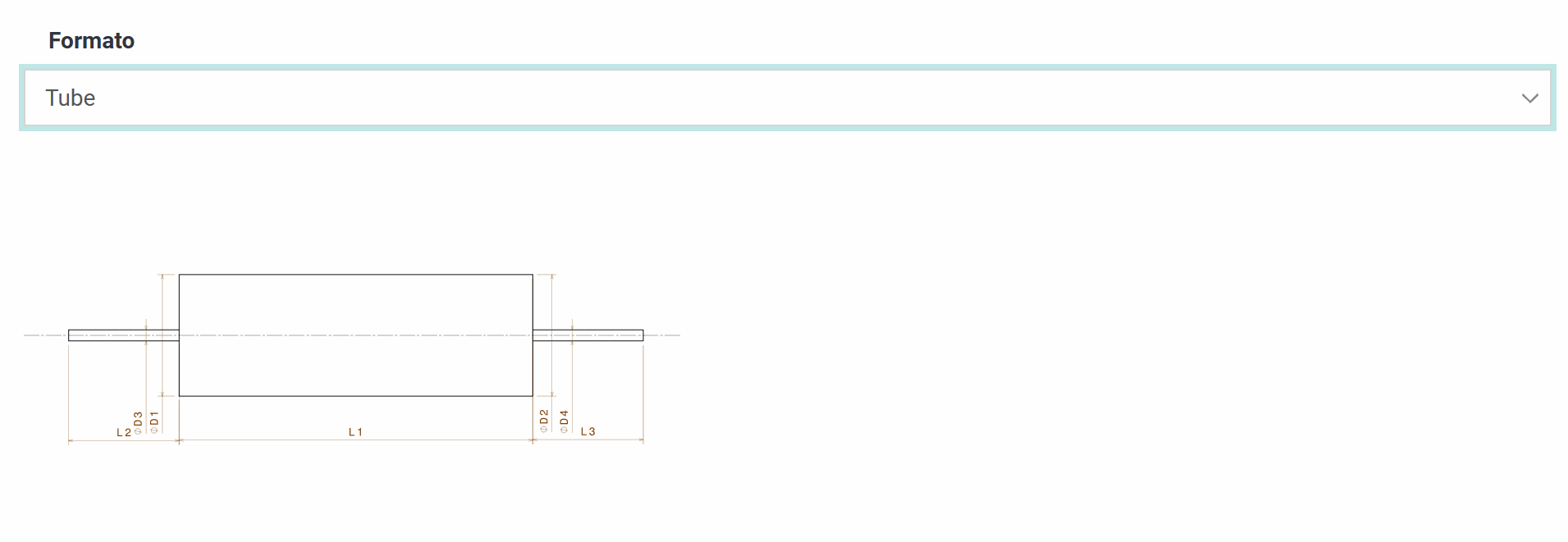
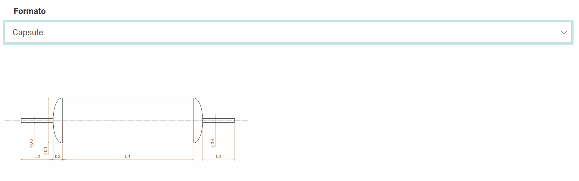
The Format dropdown offers three shapes:
- Conical — tapered from Diameter 1 to Diameter 2 along the length.
- Tube — a constant-diameter cylinder.
- Capsule — a cylindrical body with rounded or elliptical ends.
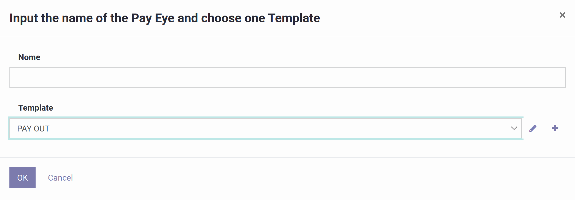
Like the mandrel, the payout eye is created through a wizard based on a template.
1) Name
Give it a name that will show up in your lists and programs, ideally noting roller type, number of rollers or machine model, for example "Payout Eye 1 - 2 Rollers".
2) Template
Pick a pre-configured payout eye template (e.g. "PAY OUT"). This automatically loads its geometry and offsets, roller/guide configuration, band-width limits and default angle or clearance values, depending on how the template was defined.
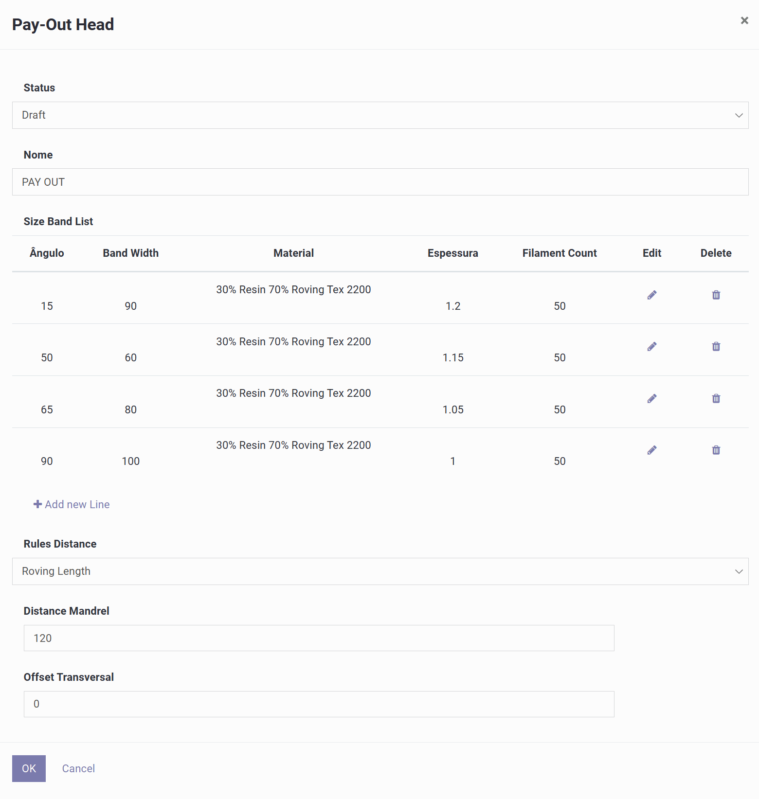
This screen configures the payout eye and the rules the software uses to calculate thickness, spacing and distance to the mandrel.
1) Header
Status shows the editable (Draft) state, and Name identifies the payout eye.
2) Size Band List
This lookup table tells the system, for a given winding angle, which band width, material, thickness and filament count to apply. Each row includes the angle (e.g. 15°, 50°, 65°, 90°), the band width, the material used, the expected layer thickness, and the filament count, with icons to edit or delete rows and a button to add new ones. This table directly drives the band width, thickness and material consumption used whenever you generate a program at a matching angle.
3) Rules Distance
Defines which rule the system uses to calculate the payout position relative to the mandrel. Three options are available:
- Roving Length — based on the real fiber path length from the payout eye to the mandrel's surface; the most geometry-accurate option, well suited to conical or capsule mandrels.
- Constant Distance from Mandrel — keeps a fixed stand-off from the mandrel surface, adjusting automatically as the local radius changes; useful when the machine should always stay a set distance from the part.
- Fixed Distance from Mandrel Central Axis — keeps a constant distance from the mandrel centerline instead of the surface; suited to machines referenced to the centerline.
4) Distance Mandrel
The stand-off distance between the payout eye and the mandrel, which affects the fiber path geometry, angle accuracy near transitions, and collision clearance.
5) Offset Transversal
The lateral offset of the payout eye relative to the mandrel centerline.
6) OK / Cancel
OK saves the payout eye configuration; Cancel discards the changes.
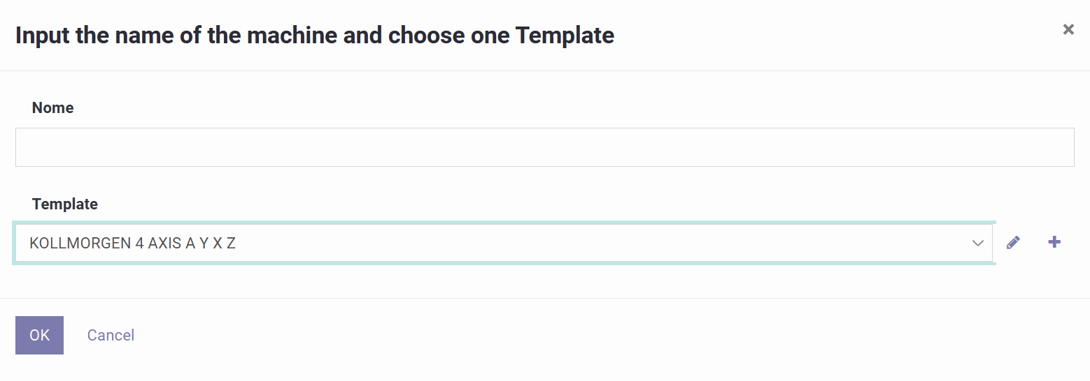
This screen is a wizard that creates a machine profile from a template, which defines its axis configuration and the post-processing behavior used when generating the program.
1) Name
Enter a name identifying the controller brand and axis set, e.g. "Kollmorgen 4-Axis FW".
2) Template
Choose a pre-configured machine template — options typically include controllers such as TexComputer, Kollmorgen (3 or 4 axis), Mach3 or LinuxCNC. A machine template defines which axes exist, what each one represents (e.g. mandrel rotation, carriage travel, approach, payout rotation), their direction conventions, units and scaling, and the output/post-processing format for that controller.
This page configures general machine settings, axis limits and speeds, and how the software writes the output program.
1) General fields
Status shows the profile's state (Draft while testing). Name and Description identify the profile. Generated File Extension sets the exported file type (.nc, .tap, .txt, .pgm) to match your controller. Unit System switches between metric and imperial for all dimensions and feed values. Friction is a coefficient used by the trajectory model.
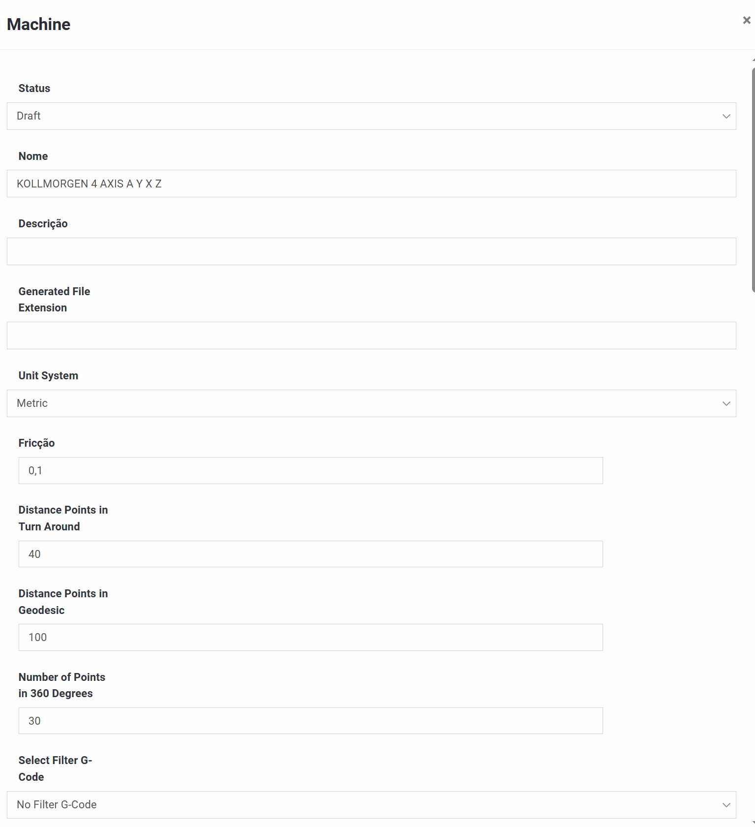
2) Trajectory resolution
Distance Points in Turn Around and Distance Points in Geodesic control point spacing (and therefore smoothness versus program size) in the turn-around zones and the regular winding zone. Number of Points in 360 Degrees sets how finely one full mandrel revolution is represented.
3) Output filtering / smoothing
An optional G-code filter can smooth the generated path. Related settings include a Smooth factor to soften sharp corners, Around Line Edit to control how many surrounding lines get adjusted, and a Reduce Lines in Linear Motion option that merges small linear segments into a lighter program.
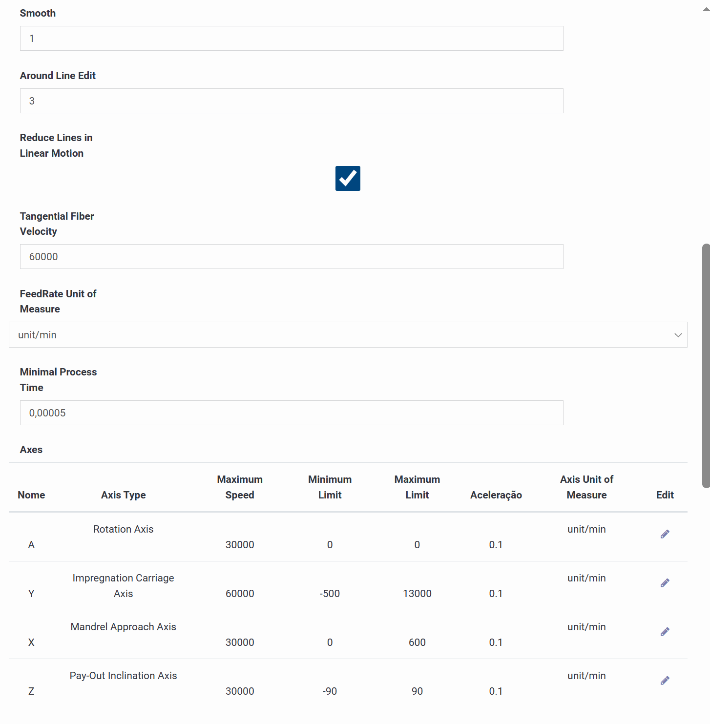
4) Speed / feed logic
Tangential Fiber Velocity sets the target surface speed used to compute feed values. FeedRate Unit of Measure must match what your controller expects (e.g. mm/min). Minimal Process Time is a safety parameter that avoids unrealistically small time steps.
5) Axes table
Each row defines an axis's type, maximum speed, minimum/maximum soft limits, acceleration and unit of measure. In a typical 4-axis setup: A is mandrel rotation, Y is the impregnation carriage travel, X is the mandrel approach distance, and Z is the payout inclination. These limits keep the generated program within the machine's physical capabilities.
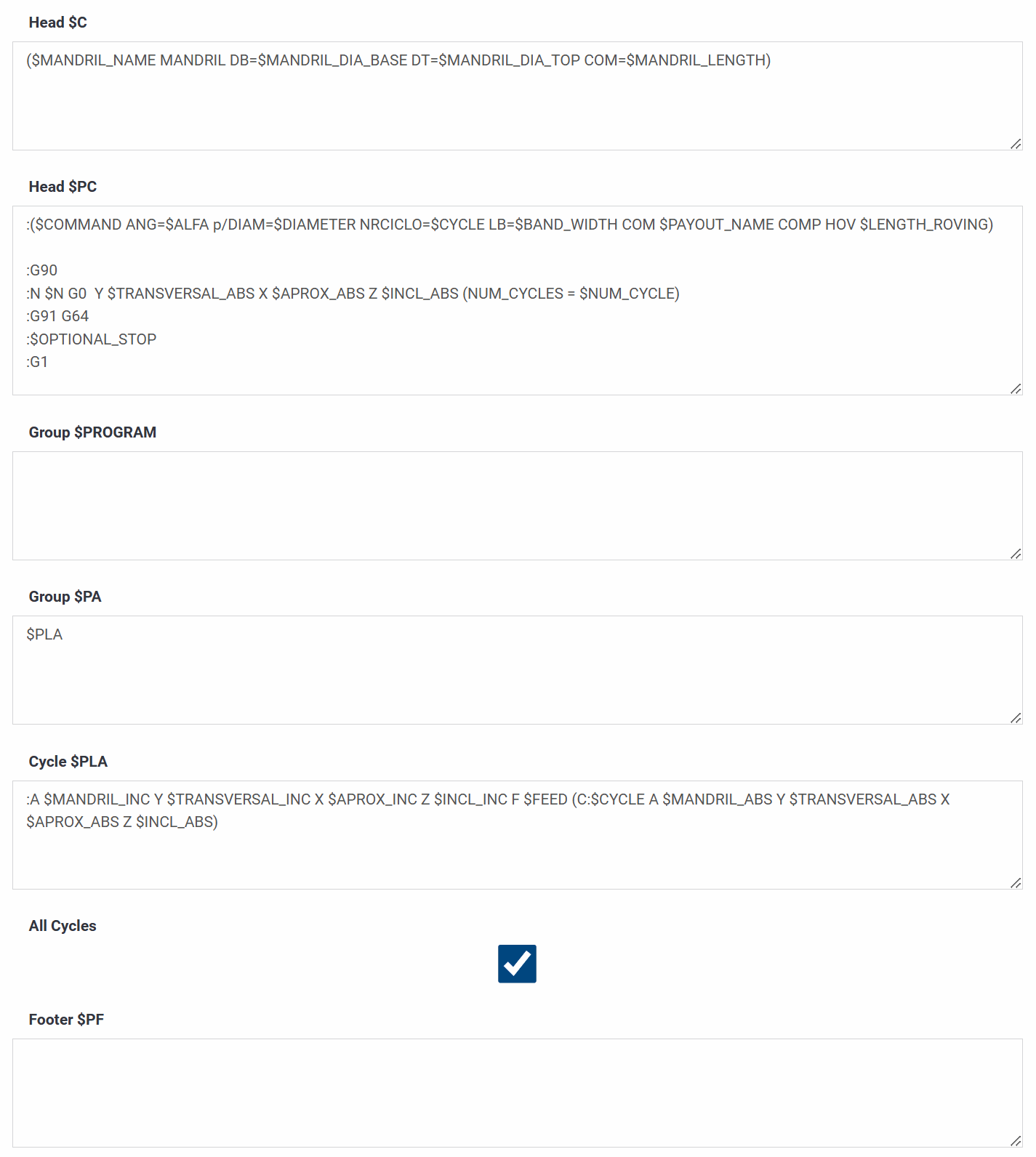
6) Post-processor blocks
Large text blocks assemble the final output file: a header comment with mandrel data, a cycle header that sets positioning modes and prints a cycle summary, subprogram and subprogram-call blocks that group repeated cycles, a footer, and a compiled preview showing the order in which all blocks are concatenated.
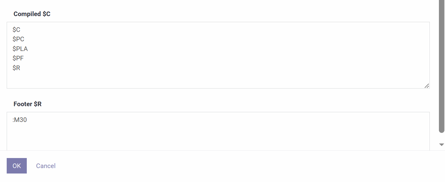
This example shows how the program text is actually built from its component blocks: headers, subprogram calls, motion lines and footers.
1) Head $C — Main Header
The first lines of the program, typically a program-start marker and number (e.g. O1000) followed by a comment filled with mandrel values such as name, base and top diameter, and length.
2) Head $PC — Cycle Header
Inserted before each winding cycle begins: a comment summarizing the cycle's angle, diameter, index, band width, payout name and roving length, followed by mode-setting commands such as G90 (absolute), a rapid positioning move, G91 (incremental) and G64 (continuous path), plus an optional stop if enabled.
3) Group $PROGRAM — Subprogram Definition
Defines the subprogram body that gets executed repeatedly, opening with a subprogram number and closing with an end-of-subprogram command (M99) after the motion line placeholder.
4) Group $PA — Subprogram Call
Tells the main program to run that subprogram a given number of times, using an M98 call with the subprogram number and a repeat count.
5) Cycle $PLA — Main Motion Line
The core multi-axis move for one incremental step of the winding: incremental values for the rotation, transversal, approach and inclination axes, a feedrate, and a trailing debug comment with the cycle number and each axis's absolute position.
6) All Cycles
When enabled, the post-processor generates all defined cycles (every angle, band width and material combination in the job), not just one.
7) Footer $PF — Main Footer
An optional block appended just before the program's final end-of-program commands.
8) Compiled $C
A preview list showing which blocks — header, cycle header, subprogram, subprogram call, footer — are concatenated, and in what order, to form the finished program.
9) Footer $R — Program End
The final termination commands, typically M30 (program end and rewind), with any prefix formatting specific to the target controller.
Program Header
Status shows whether the program is Draft or Done. Name and Description identify it, and Mandrel selects the geometry used for calculations and simulation.
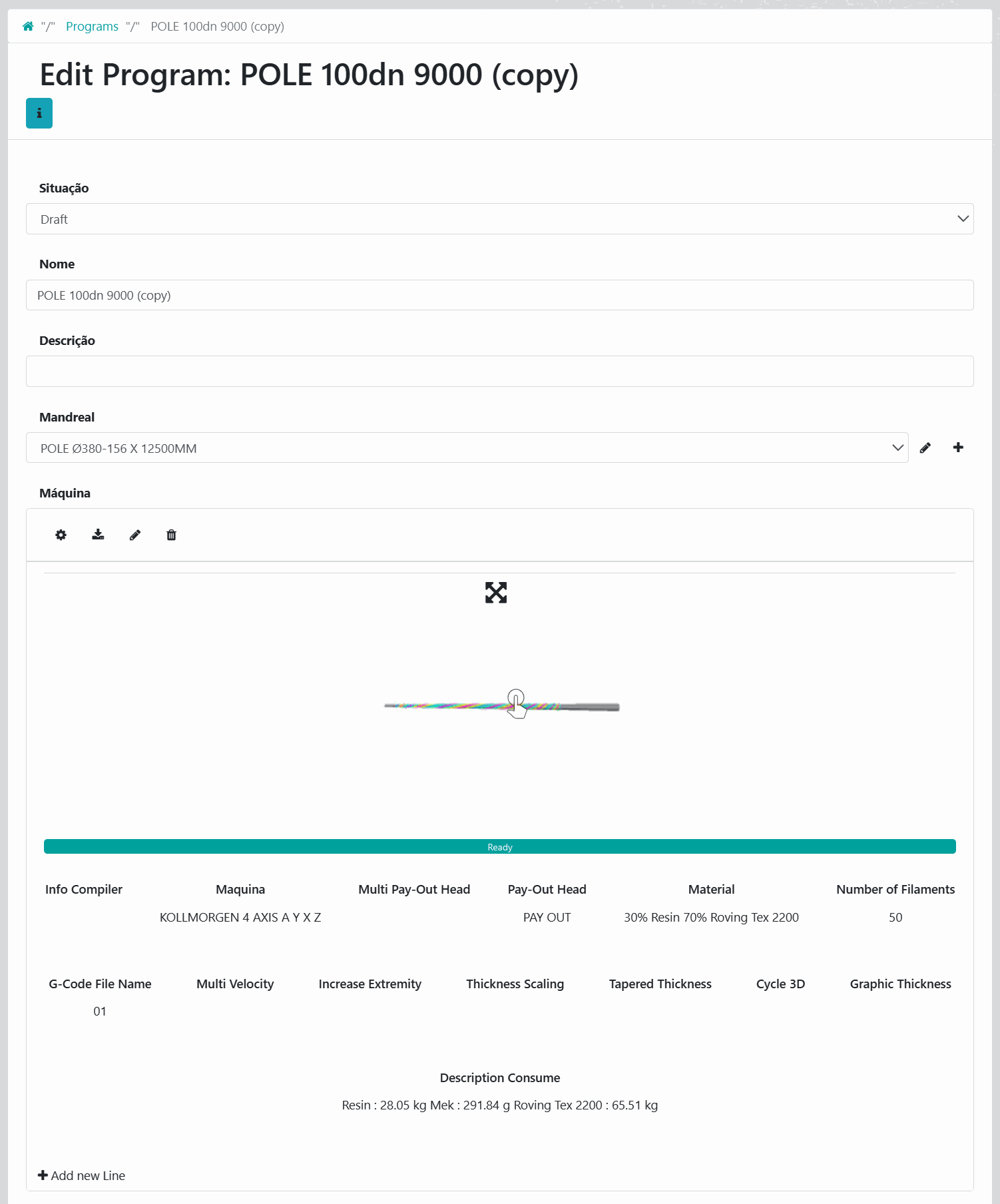
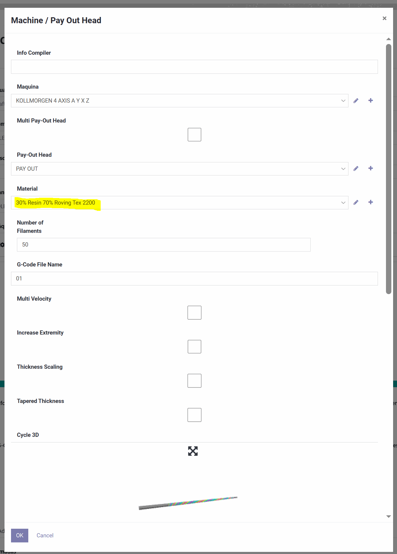
Machine / Payout Head setup
A dedicated panel defines the "compiler inputs" for the program: an optional note field, the Machine profile, a Multi Payout Head option for multi-head setups, the Payout Head configuration, the Material recipe, the Number of Filaments, and the output G-Code File Name. Optional checkboxes include Multi Velocity (variable speed logic), Increase Extremity (reinforcement near the ends), Thickness Scaling, Tapered Thickness, and Cycle 3D (3D visualization).
Layers
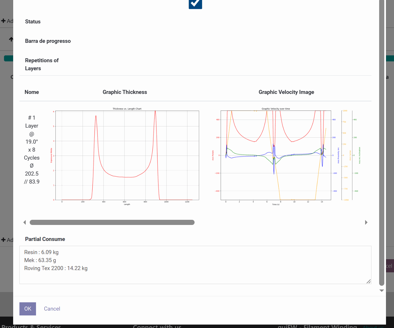
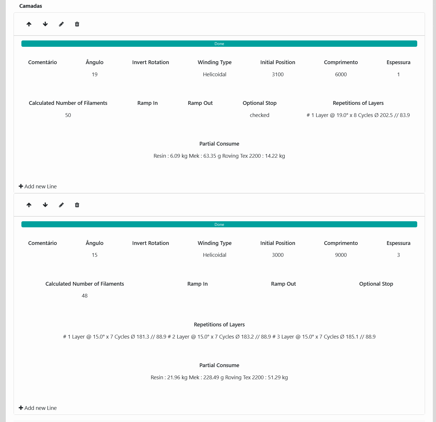
The program's recipe is a list of layers, each representing one winding operation with a comment, angle, optional rotation inversion, winding type (e.g. Helical), initial position, length, thickness, and an automatically calculated filament count. Ramp in/out and an optional stop can be set per layer, and buttons let you add, reorder, edit or delete layers. Each layer also reports partial material consumption, while the program as a whole shows total consumption.
Layer Editor
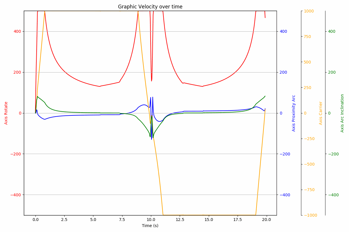
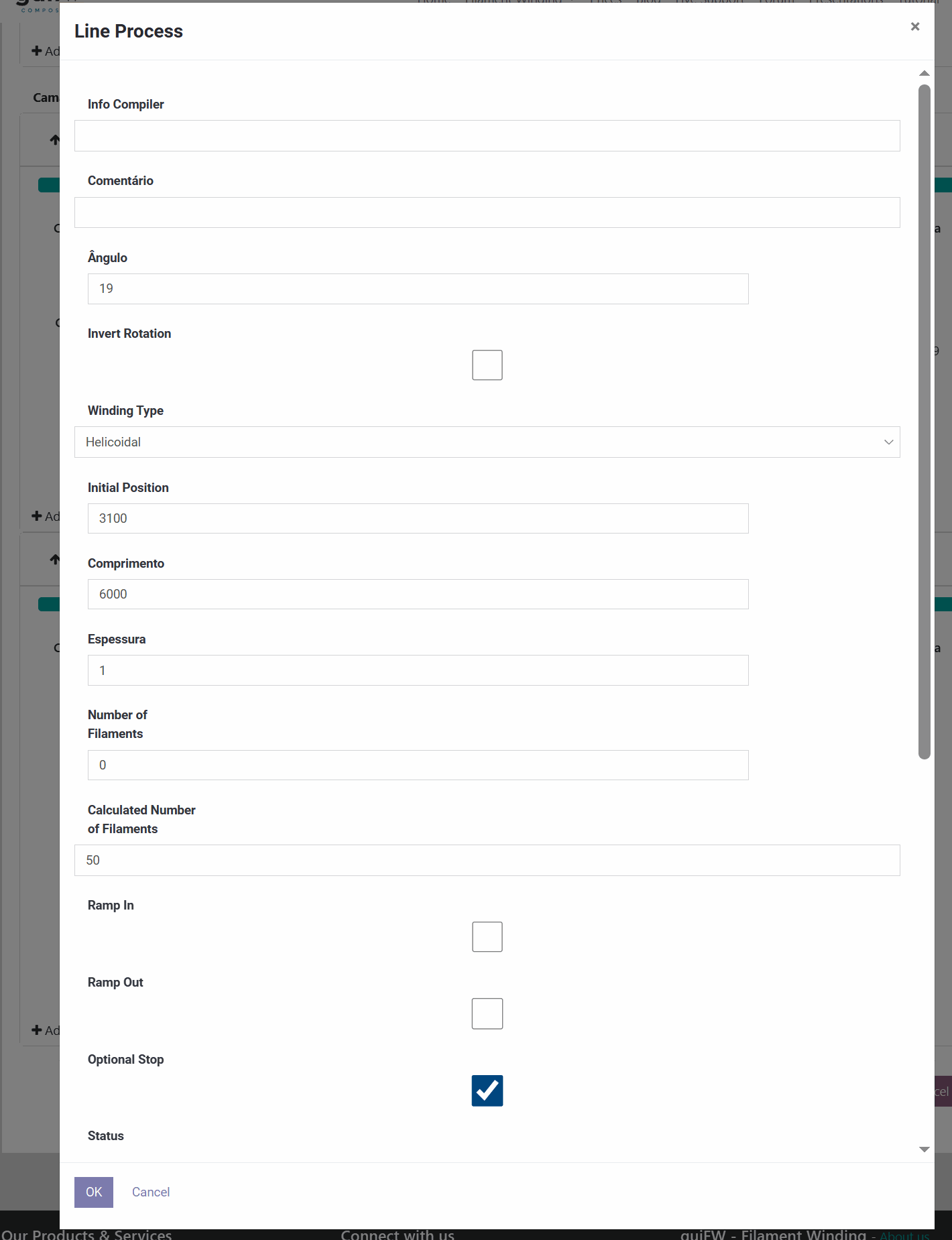
Opening a layer shows the same fields in detail — compiler info, comment, angle, rotation, winding type, position, length, thickness, filament counts, ramps and stop — plus, for that layer, a thickness-versus-length chart, per-axis velocity profiles, and a breakdown of resin, catalyst and roving consumption.