Руководство

Прежде чем создавать первую программу намотки, полезно подготовить несколько базовых вещей. Мастер программы, находящийся в разделе Filament Winding > Programs > Add a new Program, уже включает готовые шаблоны для станков, оправок, раскладчиков нити и сырья, поэтому большая часть настройки уже выполнена за вас.
Чтобы максимально эффективно использовать этот мастер, имейте под рукой следующую информацию:
- марку HMI, установленного на вашем станке, и как настроены его оси;
- тип оправки, которую вы будете использовать, и её общие размеры;
- ширину ленты, с которой работает ваш станок.
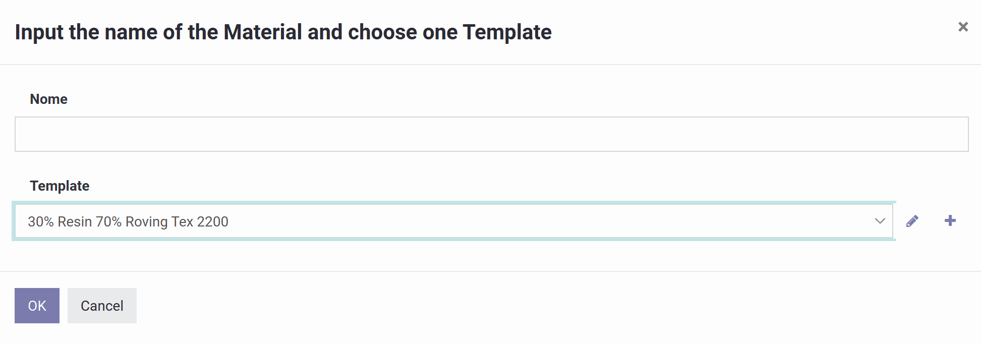
Это начальный экран для регистрации нового материала. Выбор Создать открывает форму материала, где настраивается его состав, единица измерения и спецификация материалов, как описано в следующем разделе.
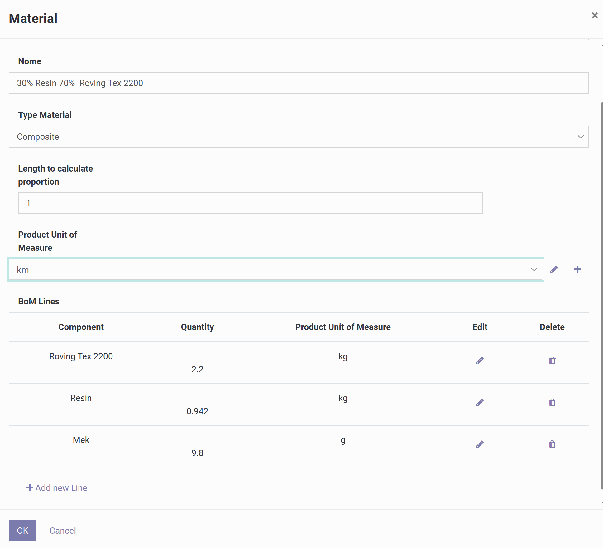
Эта форма предназначена для регистрации композитного материала и сообщает системе три вещи: что представляет собой готовый продукт, какая единица измерения используется для учёта расхода, и как выглядит рецептура (спецификация материалов).
Вот что означает каждое поле:
1) Название
Произвольная текстовая метка для материала, обычно описывающая соотношение смолы/волокна и тип ровинга, например "30% смолы 70% ровинга Tex 2200".
2) Тип материала
Установлено значение Композит, что означает, что данная запись представляет собой смесь нескольких компонентов, а не единое сырьё. Доступные типы:
- Волокно — ровинг, жгут, ткань или вуаль; учитывает расход волокна в кг, текс или г/м.
- Смола — эпоксидная, полиэфирная, винилэфирная; учитывает расход смолы в кг или л, при необходимости с плотностью для пересчёта объёма/массы.
- Препрег — волокно, уже пропитанное смолой; учитывается напрямую в м, м² или кг.
- Композит — рецептура, состоящая из нескольких компонентов, определяемая через спецификацию материалов.
- Наполнитель — твёрдые добавки, такие как кремнезём, микросферы, тальк или пигмент.
- Разделитель — разделительные агенты или плёнка, например воск, ПВА или разделительная плёнка.
3) Длина для расчёта пропорции
Определяет базовое количество, используемое для масштабирования рецептуры. Если единицей измерения продукта является длина, а это значение равно 1, приведённая ниже спецификация материалов описывает расход на 1 км готового материала; при значении 10 та же рецептура будет применяться к 10 км.
4) Единица измерения продукта
Единица, в которой измеряется готовый композит, обычно длина (км), поскольку при намотке нитью расходуется, как правило, длина ленты/ламината или длина траектории.
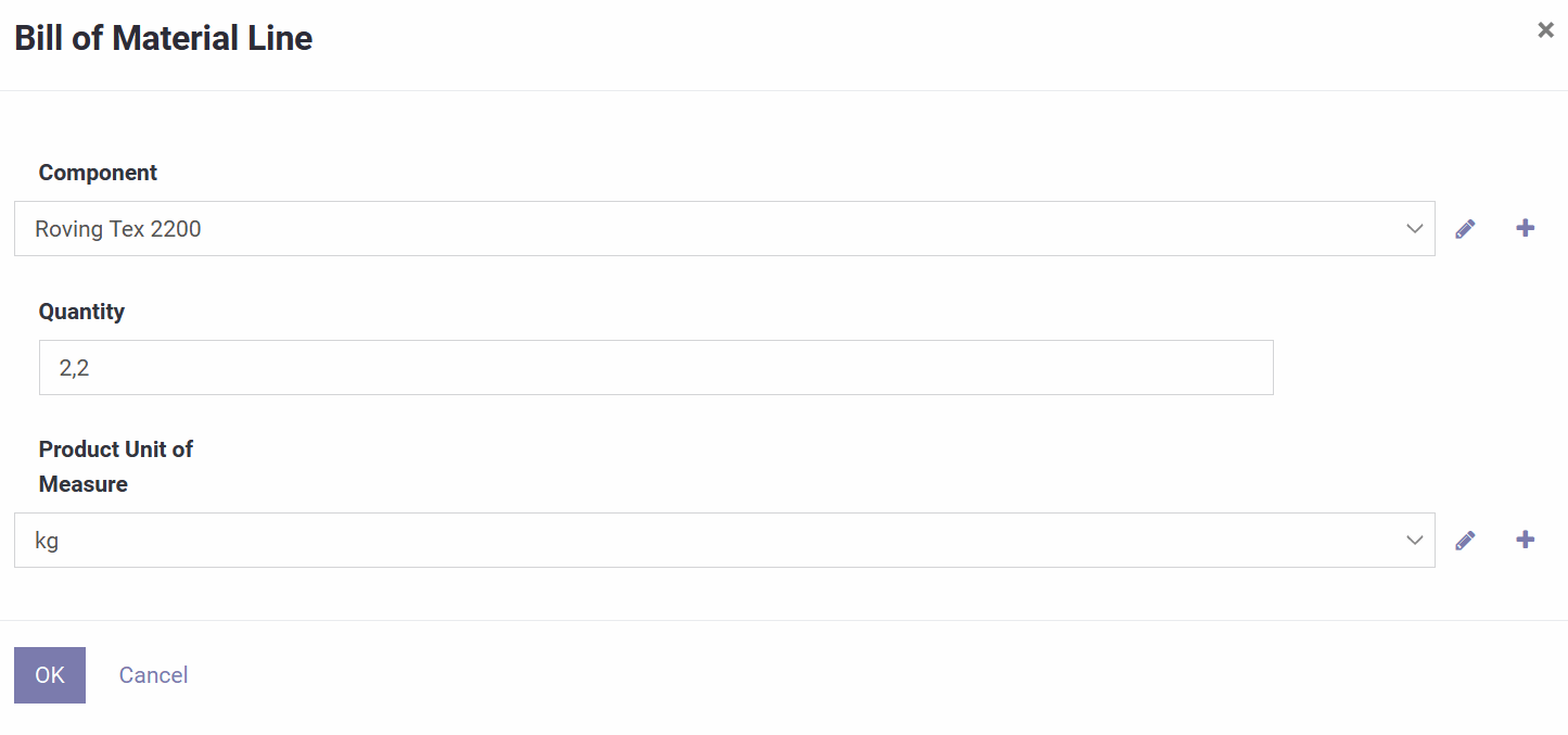
5) Строки спецификации материалов (BoM)
Собственно рецептура: каждая строка перечисляет компонент, сколько его расходуется, и его единицу измерения, с возможностью добавлять, редактировать или удалять строки. Например, на км композита: 2,2 кг ровинга Tex 2200, 0,942 кг смолы и 9,8 г МЭК (катализатора).
6) ОК / Отмена
ОК сохраняет материал и его рецептуру; Отмена отменяет изменения.
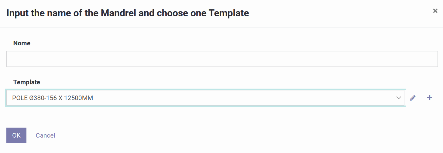
Этот экран представляет собой мастер, который создаёт оправку на основе готового шаблона.
1) Название
Метка, которая будет идентифицировать эту оправку в ваших списках и программах. Хорошие примеры включают тип, диаметры и длину, например "POLE Ø380-156 x 12500". Указание этих данных заранее облегчает распознавание оправки в дальнейшем.
2) Шаблон
Выберите преднастроенную модель оправки, например "POLE Ø380-156 X 12500MM". При выборе автоматически загружается геометрия: форма/тип, начальный и конечный диаметры, общая длина и любые другие размеры, заданные шаблоном.
Рядом с полем Шаблон значок карандаша позволяет редактировать размеры выбранного шаблона, а значок плюса позволяет создать новый шаблон для сохранения в качестве стандарта.
ОК создаёт оправку на основе выбранного шаблона; Отмена закрывает мастер без сохранения.
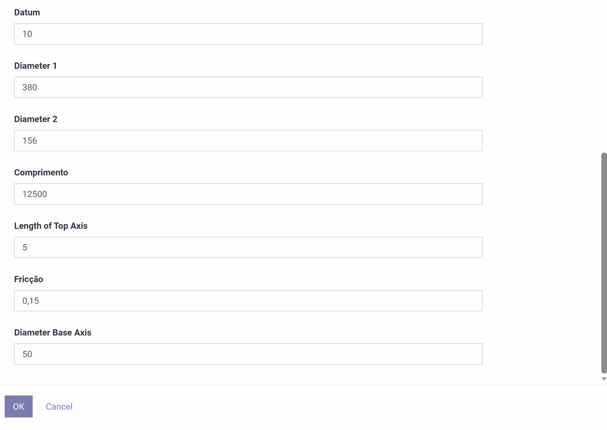
Здесь редактируется геометрия оправки, которую программное обеспечение использует для расчёта траектории намотки.
Статус показывает Черновик, пока оправка ещё редактируется. Название — это метка, отображаемая в списках и программах. Формат определяет, какая модель формы и какие размеры требуются, и соответствующим образом обновляет эскиз.
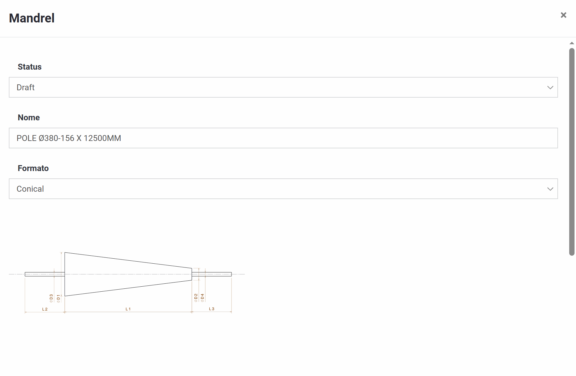
Параметры геометрии (обычно обозначаемые D1–D4 и L1–L3) напрямую влияют на эскиз, отображаемый на экране. Общие поля включают:
- База — опорное смещение, используемое как точка "ноль" для позиционирования оправки в расчётах.
- Диаметр 1 / Диаметр 2 — основные диаметры оправки. На конической оправке это большой и малый концы; на трубе они обычно равны.
- Длина — длина основного тела, используемая для намотки.
- Длина верхней оси — длина монтажного вала/хвостовика.
- Диаметр базовой оси — диаметр этого монтажного вала.
- Трение — коэффициент, используемый моделью намотки.
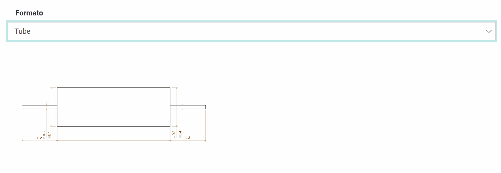
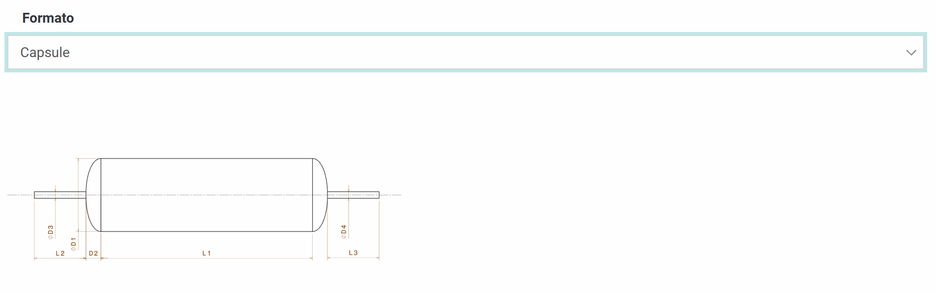
Выпадающий список Формат предлагает три формы:
- Коническая — сужается от Диаметра 1 к Диаметру 2 по длине.
- Труба — цилиндр постоянного диаметра.
- Капсула — цилиндрическое тело с закруглёнными или эллиптическими концами.

Как и оправка, раскладчик нити (раскладывающая головка) создаётся с помощью мастера на основе шаблона.
1) Название
Дайте ему название, которое будет отображаться в ваших списках и программах, желательно указав тип роликов, их количество или модель станка, например "Payout Eye 1 - 2 Rollers".
2) Шаблон
Выберите преднастроенный шаблон раскладчика нити (например, "PAY OUT"). Это автоматически загружает его геометрию и смещения, конфигурацию роликов/направляющих, ограничения ширины ленты и значения угла или зазора по умолчанию, в зависимости от того, как был определён шаблон.
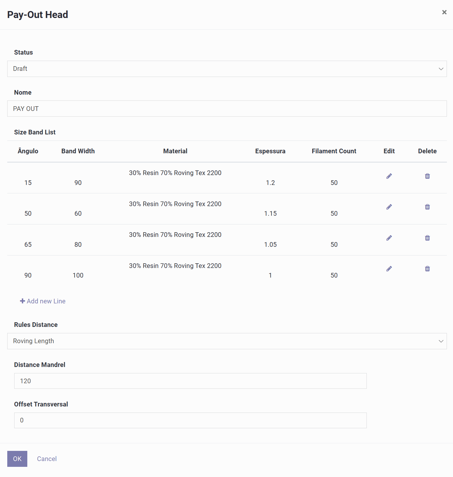
Этот экран настраивает раскладывающую головку и правила, которые программное обеспечение использует для расчёта толщины, шага и расстояния до оправки.
1) Заголовок
Статус показывает редактируемое состояние (Черновик), а Название идентифицирует раскладывающую головку.
2) Список полос по углу
Эта справочная таблица сообщает системе, какую ширину ленты, материал, толщину и количество нитей применять для заданного угла намотки. Каждая строка включает угол (например, 15°, 50°, 65°, 90°), ширину ленты, используемый материал, ожидаемую толщину слоя и количество нитей, со значками для редактирования или удаления строк и кнопкой для добавления новых. Эта таблица напрямую определяет ширину ленты, толщину и расход материала, используемые при генерации программы для соответствующего угла.
3) Правила расстояния
Определяет, какое правило система использует для расчёта положения раскладчика относительно оправки. Доступны три варианта:
- Длина ровинга — основана на реальной длине пути волокна от раскладывающей головки до поверхности оправки; наиболее геометрически точный вариант, хорошо подходящий для конических оправок или оправок-капсул.
- Постоянное расстояние от оправки — поддерживает фиксированный зазор от поверхности оправки, автоматически регулируясь при изменении локального радиуса; полезно, когда станок всегда должен оставаться на заданном расстоянии от детали.
- Фиксированное расстояние от центральной оси оправки — поддерживает постоянное расстояние от осевой линии оправки, а не от поверхности; подходит для станков, привязанных к осевой линии.
4) Расстояние до оправки
Зазор между раскладывающей головкой и оправкой, который влияет на геометрию пути волокна, точность угла вблизи переходов и зазор для предотвращения столкновений.
5) Поперечное смещение
Боковое смещение раскладывающей головки относительно осевой линии оправки.
6) ОК / Отмена
ОК сохраняет конфигурацию раскладывающей головки; Отмена отменяет изменения.
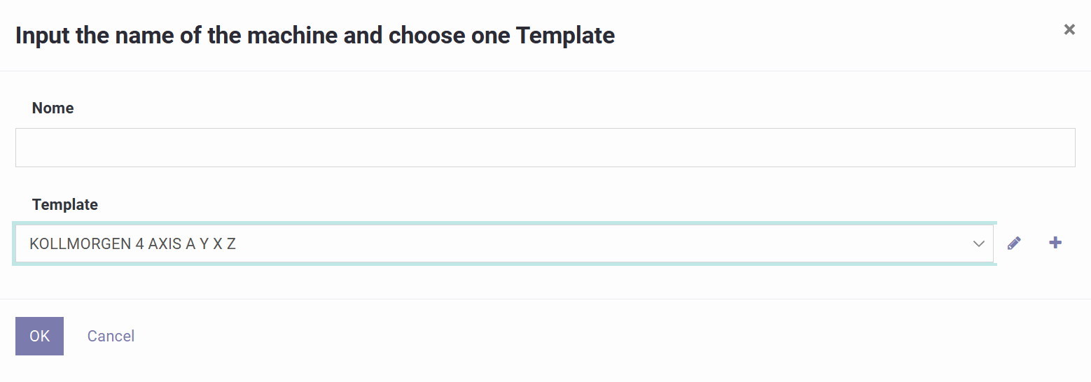
Этот экран представляет собой мастер, который создаёт профиль станка на основе шаблона, определяющего конфигурацию его осей и поведение постобработки, используемое при генерации программы.
1) Название
Введите название, идентифицирующее марку контроллера и набор осей, например "Kollmorgen 4-Axis FW".
2) Шаблон
Выберите преднастроенный шаблон станка — варианты обычно включают такие контроллеры, как TexComputer, Kollmorgen (3 или 4 оси), Mach3 или LinuxCNC. Шаблон станка определяет, какие оси существуют, что представляет каждая из них (например, вращение оправки, ход каретки, подход, вращение раскладчика), их направление, единицы измерения и масштабирование, а также формат вывода/постобработки для данного контроллера.
Эта страница настраивает общие параметры станка, ограничения и скорости осей, а также способ записи программным обеспечением выходной программы.
1) Общие поля
Статус показывает состояние профиля (Черновик во время тестирования). Название и Описание идентифицируют профиль. Расширение генерируемого файла задаёт тип экспортируемого файла (.nc, .tap, .txt, .pgm) в соответствии с вашим контроллером. Система единиц переключается между метрической и имперской для всех размеров и значений подачи. Трение — коэффициент, используемый моделью траектории.

2) Разрешение траектории
Расстояние между точками на развороте и Расстояние между точками на геодезической линии определяют шаг точек (и, следовательно, плавность по сравнению с размером программы) в зонах разворота и в обычной зоне намотки. Количество точек на 360 градусов задаёт, насколько детально представлен один полный оборот оправки.
3) Фильтрация / сглаживание вывода
Дополнительный фильтр G-кода может сгладить сгенерированный путь. Связанные настройки включают Коэффициент сглаживания для смягчения острых углов, Редактирование окружающих линий для управления количеством корректируемых соседних линий, и опцию Уменьшение линий при линейном движении, которая объединяет небольшие линейные сегменты в более лёгкую программу.
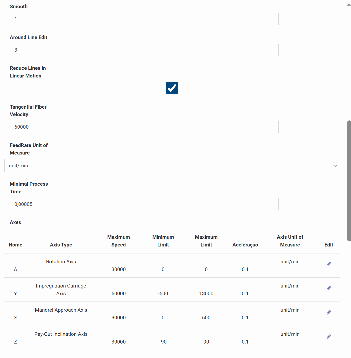
4) Логика скорости / подачи
Тангенциальная скорость волокна задаёт целевую поверхностную скорость, используемую для расчёта значений подачи. Единица измерения скорости подачи должна соответствовать тому, что ожидает ваш контроллер (например, мм/мин). Минимальное время процесса — параметр безопасности, предотвращающий нереалистично малые временные шаги.
5) Таблица осей
Каждая строка определяет тип оси, максимальную скорость, минимальные/максимальные программные ограничения, ускорение и единицу измерения. В типичной 4-осевой конфигурации: A — вращение оправки, Y — ход каретки пропитки, X — расстояние подхода оправки, а Z — наклон раскладчика. Эти ограничения удерживают сгенерированную программу в пределах физических возможностей станка.

6) Блоки постпроцессора
Крупные текстовые блоки формируют итоговый выходной файл: комментарий заголовка с данными оправки, заголовок цикла, который задаёт режимы позиционирования и выводит сводку цикла, блоки подпрограммы и вызова подпрограммы, группирующие повторяющиеся циклы, нижний колонтитул и скомпилированный предпросмотр, показывающий порядок объединения всех блоков.
Этот пример показывает, как текст программы фактически строится из составляющих его блоков: заголовков, вызовов подпрограмм, строк движения и нижних колонтитулов.
1) Head $C — Главный заголовок
Первые строки программы, обычно маркер начала программы и номер (например, O1000), за которыми следует комментарий, заполненный значениями оправки, такими как название, диаметр у основания и вверху, а также длина.
2) Head $PC — Заголовок цикла
Вставляется перед началом каждого цикла намотки: комментарий, обобщающий угол цикла, диаметр, индекс, ширину ленты, название раскладчика и длину ровинга, за которым следуют команды установки режима, такие как G90 (абсолютный), быстрое позиционирующее перемещение, G91 (относительный) и G64 (непрерывный путь), плюс необязательная остановка, если включена.
3) Group $PROGRAM — Определение подпрограммы
Определяет тело подпрограммы, которое выполняется многократно, начинаясь с номера подпрограммы и заканчиваясь командой конца подпрограммы (M99) после заполнителя строки движения.
4) Group $PA — Вызов подпрограммы
Указывает основной программе выполнить эту подпрограмму заданное количество раз, используя вызов M98 с номером подпрограммы и количеством повторений.
5) Cycle $PLA — Основная строка движения
Основное многоосевое перемещение для одного приращения намотки: приращения для осей вращения, поперечного перемещения, подхода и наклона, скорость подачи, а также завершающий отладочный комментарий с номером цикла и абсолютным положением каждой оси.
6) Все циклы
При включении постпроцессор генерирует все определённые циклы (каждую комбинацию угла, ширины ленты и материала в задании), а не только один.
7) Footer $PF — Основной нижний колонтитул
Необязательный блок, добавляемый непосредственно перед конечными командами завершения программы.
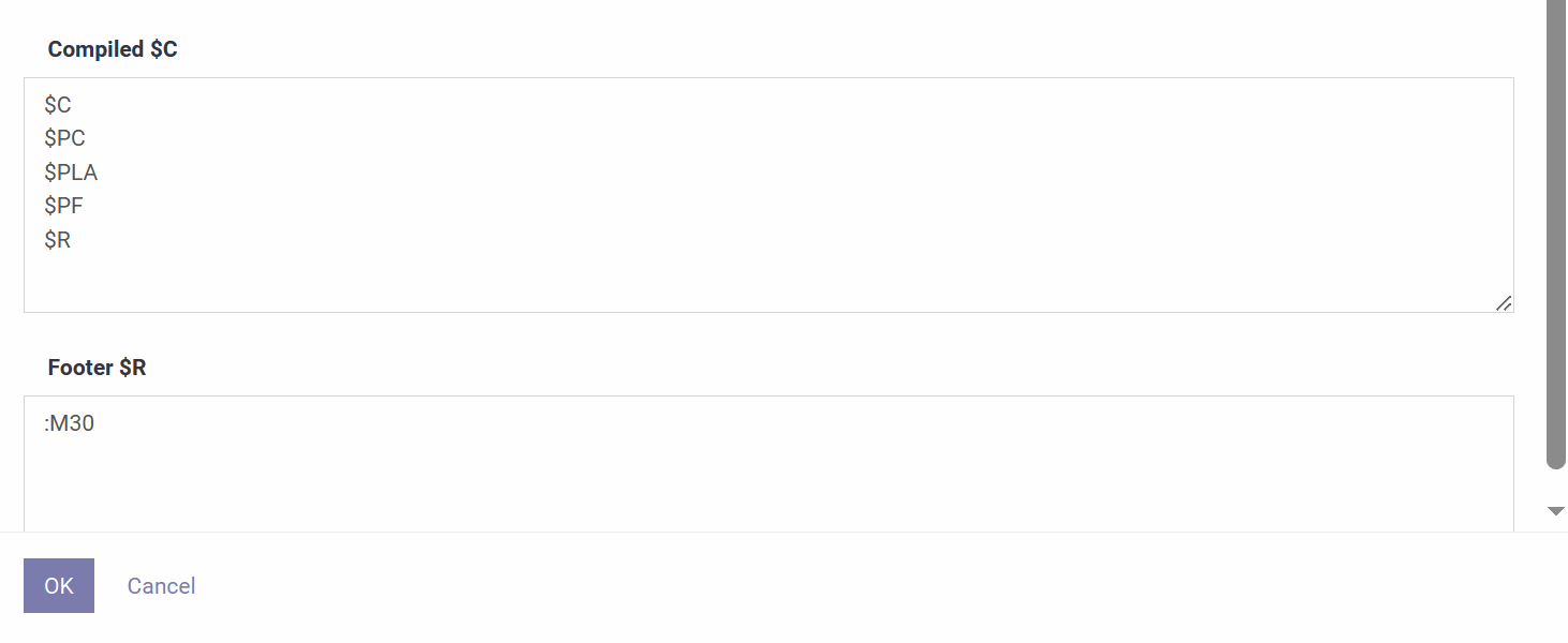
8) Compiled $C
Список предпросмотра, показывающий, какие блоки — заголовок, заголовок цикла, подпрограмма, вызов подпрограммы, нижний колонтитул — объединяются и в каком порядке, образуя готовую программу.
9) Footer $R — Конец программы
Финальные команды завершения, обычно M30 (конец программы и перемотка), с любым префиксным форматированием, специфичным для целевого контроллера.
Заголовок программы
Статус показывает, находится ли программа в состоянии Черновик или Готово. Название и Описание идентифицируют её, а Оправка выбирает геометрию, используемую для расчётов и симуляции.

Настройка станка / раскладывающей головки
Специальная панель определяет "входные данные компилятора" для программы: необязательное поле примечания, профиль Станка, опцию Мульти раскладывающая головка для многоголовочных конфигураций, конфигурацию Раскладывающей головки, рецептуру Материала, Количество нитей и выходное Имя файла G-кода. Дополнительные флажки включают Мульти скорость (логика переменной скорости), Увеличение на концах (усиление вблизи концов), Масштабирование толщины, Коническая толщина и Цикл 3D (3D-визуализация).

Слои
Рецептура программы представляет собой список слоёв, каждый из которых представляет одну операцию намотки с комментарием, углом, необязательной инверсией вращения, типом намотки (например, спиральная), начальным положением, длиной, толщиной и автоматически рассчитанным количеством нитей. Для каждого слоя можно задать разгон/торможение и необязательную остановку, а кнопки позволяют добавлять, переупорядочивать, редактировать или удалять слои. Каждый слой также сообщает частичный расход материала, тогда как программа в целом показывает общий расход.


Редактор слоёв
Открытие слоя показывает те же поля подробно — информацию компилятора, комментарий, угол, вращение, тип намотки, положение, длину, толщину, количество нитей, разгон/торможение и остановку — а также, для этого слоя, график толщины в зависимости от длины, профили скорости по осям и разбивку расхода смолы, катализатора и ровинга.

